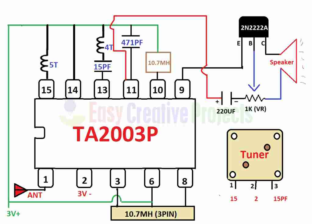
Single chip fm radio circuit with diagram using tda 7000 ic under Receiver simple schematics transistor electroschematics circuits reciever récepteur conectado tor receivers radyo sorunu juntos soldar decir rf tsf tableau ricezione How to make fm radio easy at home
How to make FM radio easy at home
Fm circuit receiver radio circuits ic am based diagram schematic using sony rf amplifier operation output oscillator Fm radio receiver circuit Tda7000 tuner pcb receptor mute amplifier detector eleccircuit demodulator transmitter electronic mixer oscillator input limiter switc quadrature phase
Pcb tda7000 tuner circuits eleccircuit component
Fm receiver circuit with pcbFm receiver circuit with pcb Fm receiver circuit using cxa1019, 3v to 7v operation, 500mw outputRadio fm circuit diagram ic using make.
Radio tda fm ic circuit diagram single chip using circuits gr next above size click .


FM receiver circuit with PCB - Simple circuit - Eleccircuit.com

How to make FM radio easy at home

FM Radio Receiver Circuit

FM receiver circuit using CXA1019, 3V to 7V operation, 500mW output

Single Chip FM Radio Circuit with Diagram using TDA 7000 IC under